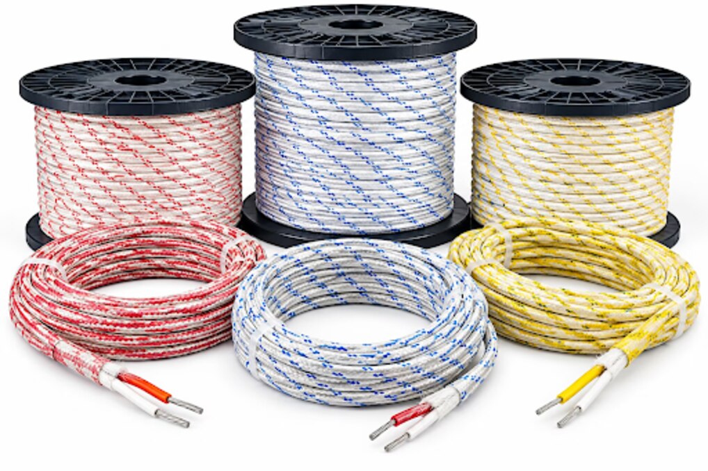
A thermocouple extension cable is not simply a heat-resistant wire: its conductor alloys, polarity, accuracy class, insulation, shielding, and termination all affect the reading. By the end, you will be able to define the cable specification, identify installation risks, and compare a manufacturer’s proposal against the requirements of your sensor and instrument.
Key takeaways
- Match the extension cable to the sensor’s thermocouple type and polarity.
- Use thermocouple-grade or extension-grade conductors suited to your accuracy requirements.
- Select insulation and shielding for the route’s heat, moisture, movement, and interference.
- Give suppliers the cable length, resistance, construction, terminations, and operating conditions.
Start with the thermocouple type, cable grade, and accuracy standard
A true thermocouple extension cable must match the sensor’s type and polarity: J, K, T, E, N, R, S, or B. Name that type before requesting a quotation. Copper or a superficially similar alloy can create extra thermocouple junctions, producing an error that changes with temperature.
| Option | What it means | When it applies |
|---|---|---|
| Thermocouple-grade wire | Uses the sensor’s nominal thermoelectric materials | The cable enters a hot zone or needs the full qualified range |
| Extension-grade wire | Reproduces the thermocouple type over a specified, usually narrower, range | The cable remains within its stated extension range |
| Thermocouple compensating cable | Uses substitute alloys matched only across a stated range | The quotation identifies that range and its limitations |
Do not accept “thermocouple cable” as a complete description. Ask for IEC 60584-3 compliance for extension or compensating cable, then evaluate thermocouple performance against IEC 60584-1 reference functions and tolerances. ASTM E230/E230M provides the corresponding US materials and reference tables.
- Specify the tolerance class, operating range, conductor polarity, and governing standard.
- State whether the cable will enter the hot zone. A high insulation-temperature rating does not prove that extension-grade alloys remain accurate at that temperature; use thermocouple-grade wire until the cable temperature falls within the extension cable’s qualified range.
- Request the alloy designation and conformity document. Confirm that the quoted product is an extension cable or a thermocouple compensating cable, not ordinary high-temperature hookup wire.
Preserve polarity and control every junction in the signal path
A reversed pair can turn an accurate sensor into a large error, and the error changes with the temperature difference between the measuring junction and instrument terminals. Identify the positive and negative conductors from the manufacturer’s datasheet and named colour standard, not colour memory.
IEC 60584-3 and ANSI/ASTM practice use different conventions, so put the standard and thermocouple polarity in the purchase specification. Mark + and − at the sensor, every connector, each terminal block, and the instrument. A continuity or resistance test will not reveal reversed conductors.
| Junction choice | Benefit | Risk or requirement |
|---|---|---|
| Grounded thermocouple junction | Faster response | Ground loops and common-mode interference |
| Ungrounded thermocouple junction | Electrical isolation | Greater thermal mass and slower response |
Keep the same thermocouple materials through connectors and splices while the cable remains in the thermoelectric circuit. Copper terminals work only when both conductors enter an isothermal instrument terminal area where the instrument performs cold-junction compensation. A terminal block across a temperature gradient adds error because every dissimilar-metal junction contributes to the thermoelectric loop.
Confirm that the instrument supports the named thermocouple type, measures terminal temperature, and applies cold-junction compensation. The extension cable does not perform CJC, despite claims such as “CJC compatible.” Specify whether the sensor uses a grounded thermocouple junction or an ungrounded junction before ordering connectors and control hardware.
Choose insulation and shielding for the actual route, not the highest temperature number
Measure the actual ambient temperature at the cable, not just the process temperature. Select thermocouple insulation for that temperature plus abrasion, moisture, oil, solvents, furnace atmosphere, flexing, and dielectric requirements; a high insulation rating does not prove that extension-grade alloys remain accurate there.
| Construction | Strength | Limitation |
|---|---|---|
| Fiberglass thermocouple cable | High heat and abrasion resistance | Fiberglass and braid are not a sealed moisture barrier |
| PTFE or PFA | Chemical exposure and smooth routing | Less suitable where severe abrasion or repeated flexing dominates |
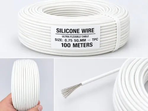
| Silicone | Flexibility | Verify its temperature and abrasion ratings |
| PVC | Economical fixed routing | Use only within its specified temperature and chemical limits |
| Ceramic-fibre or mineral-insulated thermocouple cable | Hotter furnace or pipe sections | Mineral-insulated construction is less flexible and needs suitable termination |
Add conduit, sleeving, or mechanical protection where water, oil, sharp edges, or movement threatens fiberglass. For a furnace or heated pipe, run thermocouple-grade wire or mineral-insulated thermocouple cable until the measured cable temperature falls inside the extension cable’s qualified alloy range. Set that transition point from cable temperature, not distance from the heat source.
Keep the pair away from power, motors, heaters, and variable-frequency-drive wiring. Cross unavoidable power routes at 90 degrees, keep the conductors twisted, and use shielded thermocouple cable when capacitive pickup remains a risk. Terminate the shield according to the instrumentation design, commonly at one end, so it does not create a ground-current path.
Shielding cannot fix wrong alloys or reversed polarity.
Size the cable for distance, resistance, movement, and termination
Measure the complete thermocouple cable length, including service loops, bends, vertical runs, and the sensor-to-instrument distance. State the total loop length, thermocouple conductor size, instrument input resistance, and sensor’s allowable loop resistance.
A long run increases resistance, noise pickup, and input-bias error; a larger conductor lowers resistance but adds cost, diameter, weight, heat leakage, and termination space.
| Conductor choice | Use it when | Main trade-off |
|---|---|---|
| Solid thermocouple wire | The route is fixed and the terminal accepts solid conductors | Lower flexibility; repeated movement can break it |
| Stranded thermocouple wire | Vibration, drag chains, or repeated flexing is present | More termination care and slightly greater handling complexity |
| Matched pair | The circuit is a basic two-wire thermocouple | No spare cores for shields, dual sensors, or transmitters |
| Additional cores | The circuit includes a grounded shield, reference conductor, dual sensor, or transmitter | Larger cable and more termination space |
Specify insulation outside diameter, minimum bend radius, braid coverage, maximum cable temperature, and chemical exposure. Select the temperature rating from the cable location, not the process temperature; high-rated insulation does not prove that extension alloys remain accurate at that temperature.
Match thermocouple connectors to the type and polarity. Confirm whether the instrument accepts bare conductors, miniature plugs, DIN terminals, or a transmitter input. Put the sensor junction type, cable grade, tolerance class, colour standard, conductor size, shield termination, route length, and maximum cable temperature on the purchase order.
Turn the installation findings into a supplier-ready cable specification
Send thermocouple cable manufacturers one schedule, not a product name. Your thermocouple cable specification must tie the alloy, accuracy, route temperature, and terminals to the installation record.
| Cable type | What it means | When it applies |
|---|---|---|
| Extension-grade | Matched type over a stated range | Cool routes outside the hot zone |
| Thermocouple-grade | Sensor-matching alloys over the qualified range | Hot sections or higher accuracy |
| Compensating | Substitute alloys over a limited range | Only when its stated range fits |
Include:
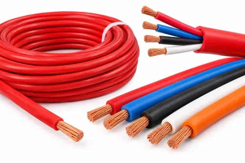
- Sensor type; extension or thermocouple grade; IEC 60584-3 or ASTM E230/E230M basis; tolerance class; IEC or ANSI polarity convention; conductor cross-section; core count; stranded or solid construction; total route length; maximum cable temperature; insulation material; braid or shield; flexing requirement; chemical exposure; and connector style.
- Request the conductor-alloy designation, operating range, resistance per metre, insulation rating, shield-termination recommendation, batch identification, and a test or conformity document.
Rewari Cable Industries is useful to compare here as a high-temperature electrical cable supplier that can discuss the complete sensor-to-instrument route, not insulation temperature alone. Compare each submission independently against your alloy, standard, tolerance, route temperature, and terminal requirements.
Before commissioning, trace + and − end to end, tighten terminals, inspect splices, measure continuity, verify the instrument setting and CJC function, then compare the reading with a reference source at a known temperature. This thermocouple cable testing catches reversed conductors and incorrect configuration that resistance testing misses.
Related products
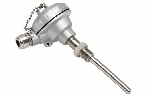
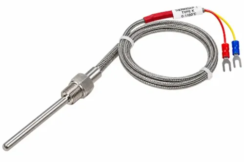
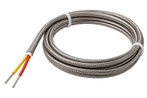
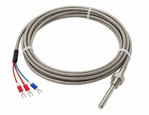
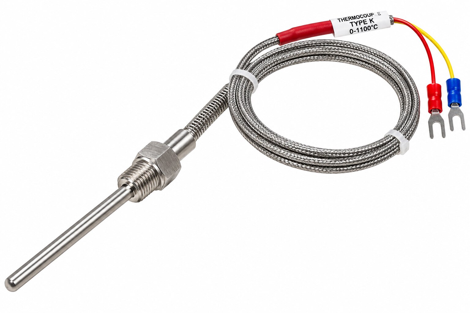 | Thermocouple Sensor Manufacturer & Supplier Rewari Cable Industries offers reliable and high-quality Thermocouple Sensors designed for accurate temperature measurement... View product → |
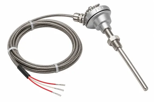
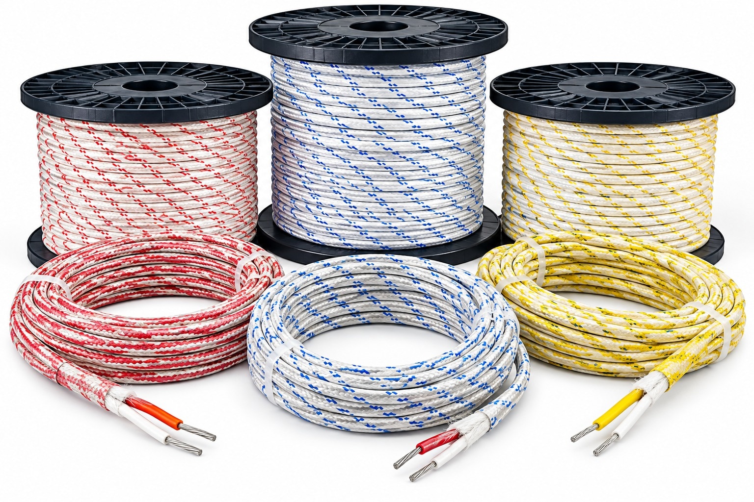 | Thermocouple Fiber Cable Rewari Thermocouple Fiber Cable Rewari Rewari Cable Industries offers high-quality Thermocouple Fiber Cables designed for temperature measurement and signal transmission in demanding... View product → |
Frequently asked questions
How do you choose the correct thermocouple extension cable?
Start with the sensor type—J, K, T, E, N, R, S, or B—then specify cable grade, accuracy standard, polarity, insulation, shielding, length, resistance, movement, and terminations.
Why must thermocouple cable polarity be preserved?
Reversing the positive and negative conductors changes the measured signal. Avoid copper substitutions and verify conductor markings at every connection.
How should you choose thermocouple cable insulation and shielding?
Choose insulation for the actual route’s temperature, moisture, chemicals, abrasion, and flexibility. Add shielding when nearby drives, motors, or power cables could introduce electrical noise.
What information should you send to a thermocouple cable supplier?
Provide thermocouple type, cable grade, accuracy standard, conductor size, length, insulation and shield construction, temperature exposure, movement, routing conditions, and connector or termination details.
Related products
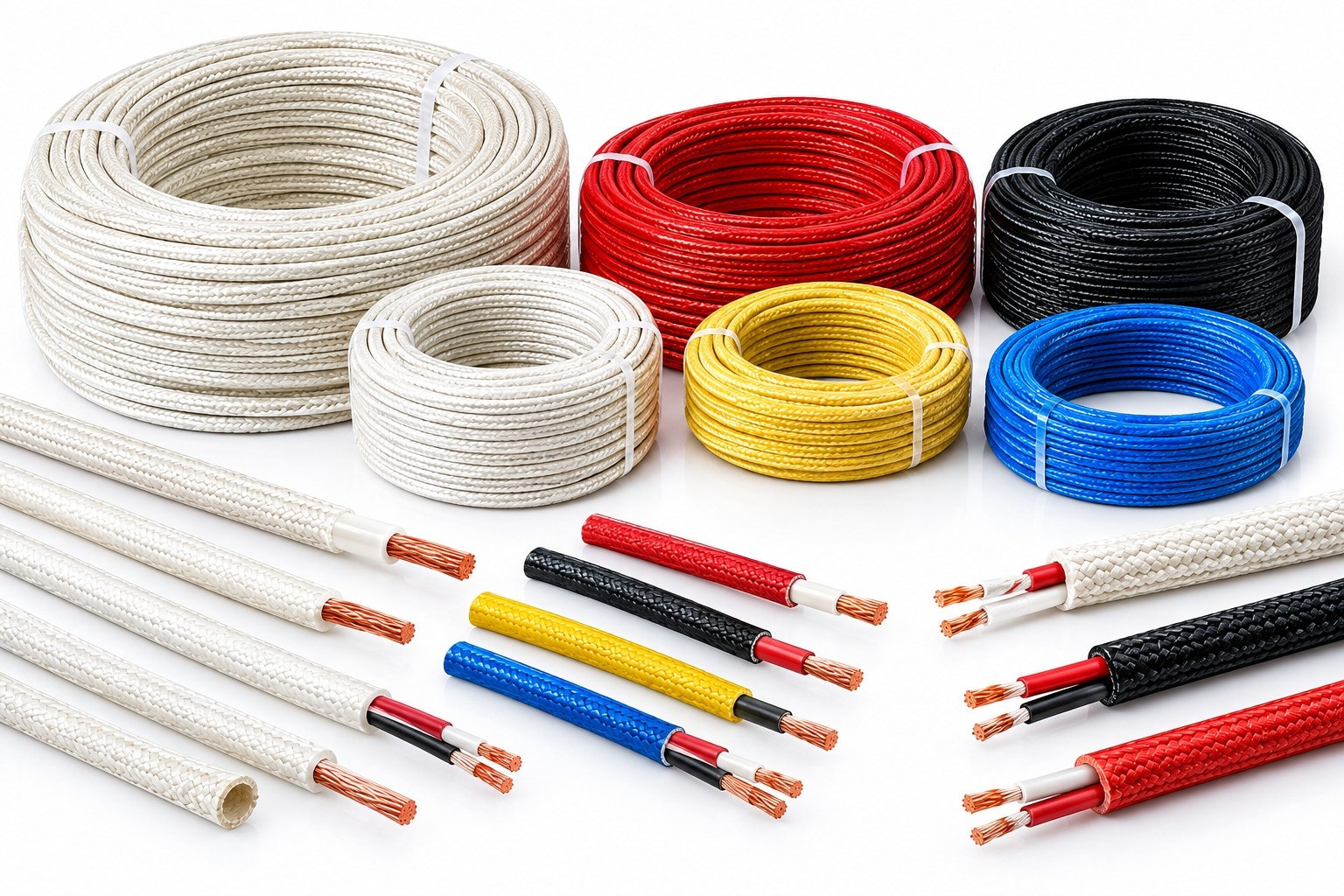 | Fiberglass Cable Rewari Cable Industries Fiberglass Cables and Fiberglass Insulated Wires are designed for electrical and industrial applications requiring... View product → |
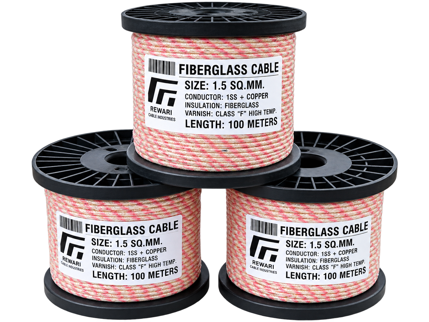 | Fibreglass Cable Rewari Cable Industries manufactures high-quality Fibreglass Cables designed for electrical applications requiring excellent heat resistance,... View product → |
 | PTFE Teflon Cable Rewari Cable Industries offers PTFE Teflon Cables designed for electrical wiring and industrial applications where high-temperature performance,... View product → |