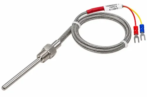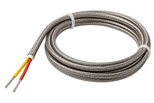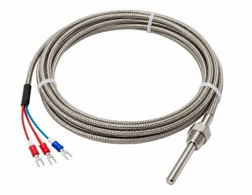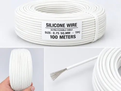
An RTD loop can show the wrong process temperature even when the sensing element is accurate: lead resistance, mismatched conductors, noise, poor grounding and unsuitable terminations all affect the final reading. By the end, you will be able to specify the sensor, cable, connection method and receiving instrument as one measurement system rather than buying a cable by insulation type alone.
Key takeaways
- Use 3-wire wiring for practical lead-resistance compensation in industrial installations.
- Choose 4-wire Pt100 measurement when maximum accuracy matters.
- Keep cable temperature rating, shielding and conductor resistance within loop limits.
- Match the RTD curve, wiring method and input configuration before ordering.
How lead resistance changes a Pt100, Pt500 or Pt1000 reading
An RTD converts temperature into resistance, and the instrument converts that resistance back into temperature through a selected curve. Under IEC 60751, a Pt100 is 100 Ω at 0 °C with a nominal coefficient of 0.00385 Ω/Ω/°C. Pt500 and Pt1000 are 500 Ω and 1,000 Ω at 0 °C.
| Sensor | Resistance change per degree | Effect of a fixed lead resistance |
|---|---|---|
| Pt100 | Lowest | Largest proportional error |
| Pt500 | Five times Pt100 resistance | Smaller proportional error |
| Pt1000 | Ten times Pt100 resistance | Smallest proportional error |
A two-wire circuit adds the resistance of both copper leads to the sensor value. Long runs, small conductors, unequal lengths, terminal resistance and hot junctions therefore create temperature error. Higher-resistance elements reduce that error proportionally, but do not make cable selection irrelevant.
Pt100, Pt500 and Pt1000 compatibility depends on the transmitter or controller input range and selected curve, not the cable name. RTD self-heating follows P = I²R; excessive measuring current raises the element temperature and creates a false reading.
Specify these items before ordering:
- IEC 60751, resistance value, measuring current and cable arrangement.
- IEC 60751 tolerance class A and B: Class A is ±(0.15 + 0.002|t|) °C; Class B is ±(0.30 + 0.005|t|) °C. Tolerance widens away from 0 °C.
- Maximum lead resistance, length, conductor size and terminal details.
- Whether the stated accuracy covers only the element or the complete loop, including leads, transmitter and input scaling.
When 2-wire, 3-wire and 4-wire connections are the right choice
Choose the wiring arrangement by the lead-resistance error your process can tolerate: 2-wire RTD for short runs, 3-wire RTD for most industrial installations, and 4-wire RTD for the smallest measurement uncertainty.
| Connection | Terminals and measurement | Right choice |
|---|---|---|
| 2-wire RTD | One pair to RTD transmitter terminals, PLC input or digital temperature controller terminals marked RTD+, RTD−, or equivalent; element and both lead resistances are measured together | Short cable where the added resistance stays within the accuracy requirement |
| 3-wire RTD | Two conductors on one side of the element and one on the other, connected to the three dedicated RTD terminals shown in the wiring diagram | General-purpose process monitoring when same-side leads match closely in material, gauge, length and temperature |
| 4-wire RTD | Two current leads and two voltage-sensing leads on four separate terminals; the voltage circuit draws negligible current | Long runs, laboratory work or tight accuracy limits where lead resistance must have minimal effect |
A 3-wire circuit’s lead compensation fails when one conductor is longer, thinner, hotter or made from different material. Specify maximum run length, conductor resistance and lead matching, not just “3-wire.”
Match the sensor termination to the receiving device. Do not join wires to force a 3-wire sensor into a 4-wire input until the instrument manufacturer confirms the circuit. Ask whether calibration includes the installed lead assembly; otherwise the stated sensor accuracy excludes a significant part of the loop.
How to specify cable construction for temperature, voltage and signal integrity
Specify the cable as a complete electrical assembly, not only by its insulation label. Request the conductor material, conductor cross-section in mm² or AWG, insulation thickness, insulation temperature rating, allowable voltage and insulation-resistance test method.
Record the RTD silicone cable temperature rating, but apply it only to the cable insulation: the RTD element, seal, transition, connector and instrument terminals each have separate limits.
| Option | Construction | Confirm before purchase |
|---|---|---|
| Silicone-insulated lead wire | Flexible routing at its stated temperature limit | Insulation thickness, allowable voltage and test method |
| Mineral-insulated RTD cable | Metal-sheathed routing for higher temperatures | Sheath material, moisture sealing, minimum bend radius and insulation-resistance limit |
| High-temperature lead wire | Alternative for conductors between the element and cold termination | Continuous temperature rating and termination temperature limit |
Mineral insulation does not prove leak-free service after a damaged seal or poor termination. Ask whether the cable is shielded, twisted, screened and fitted with a drain wire.
Twisted pairs reduce loop area; shielding helps near heaters, motors and a variable-frequency drive, but grounding both ends without a site grounding design can create a ground loop.
- Route RTD wiring separately from motor feeders, heater circuits and heat-trace wiring.
- Confirm hazardous-area requirements, intrinsic-safety barriers or galvanic isolation where applicable.
- Check that the cable’s allowable voltage is not being mistaken for the circuit’s hazardous-area approval.
How to match the complete RTD loop to the instrument and installation
Prevent compatibility and response-time failures with complete RTD sensor transmitter matching, not cable selection alone. Match the Pt100, Pt500 or Pt1000 curve, 2-wire, 3-wire or 4-wire arrangement, and Class A or Class B tolerance to the transmitter, PLC analog input, digital temperature controller or temperature input module.
1. Confirm the receiving instrument’s RTD input range, terminal size, connector type and input excitation current. Follow its wiring diagram exactly; an instrument that accepts Pt100 does not automatically accept Pt500 or Pt1000.
2. Check whether it accepts Callendar–Van Dusen coefficients. Enter those coefficients, or the supplied calibration table, into the transmitter or control system. Without that step, the instrument uses the generic IEC curve and discards much of the custom calibration.
3. Request calibration points that bracket the operating range. Treat sensor calibration separately from a loop test covering wiring, transmitter linearization, input-card scaling and display error.
4. Set the cable-run limit from the instrument’s lead-compensation and resistance limits. A head-mounted transmitter at the sensor or a DIN-rail transmitter near the process reduces lead-error exposure on long runs.
5. Match the sensor to its thermowell: verify sheath diameter and material, insertion length, bore clearance, pressure rating and fluid compatibility. Thermowell response time depends on mass, mounting and flow, so T63 and T90 data is useful only when the test medium and mounting arrangement are stated.
What a reliable wire-type RTD manufacturer should document before supply
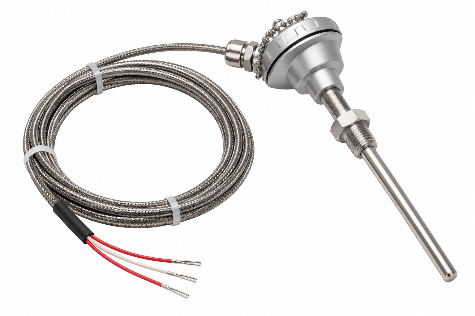
A reliable wire-type RTD manufacturer documents the complete assembly before supply; a catalogue temperature rating alone cannot reveal lead mismatch, a weak transition, or an incompatible input. Put this wire-type RTD sensor procurement specification in the purchase order and require RTD manufacturer documentation.
- Request the RTD cable datasheet, termination drawing, and a drawing identifying the element, 2-wire, 3-wire or 4-wire lead configuration, conductor material, cross-section, insulation thickness, overall diameter, transition, termination, and strain relief.
- Record the temperature range and voltage rating for every section, including the element, seal, transition, connector, and outer cable. Require IEC 60751 conformity, or the named element standard, with its tolerance.
- Require lead matching for 3-wire assemblies, maximum recommended run, insulation resistance and test method, shield construction, drain-wire arrangement, minimum bend radius, and sealing method.
- For noisy plants, obtain grounding instructions and minimum separation from power cables, heaters, and variable-frequency drives.
- For high-temperature or vibrating service, ask for thermal-cycling results, mechanical support, spring loading, vibration provisions, and the transition’s upper continuous temperature.
| Configuration | Evidence to request | Main risk controlled |
|---|---|---|
| 2-wire | Lead resistance and run limit | Added resistance error |
| 3-wire | Resistance match between same-side leads | Incomplete compensation |
| 4-wire | Four-terminal termination and instrument compatibility | Incorrect excitation or sensing |
Rewari Cable Industries can be evaluated on this evidence when sourcing RTD wiring with related temperature and control components. Compare the complete datasheet, termination drawing, sensor assembly test record, and instrument compatibility statement—not a catalogue label—so supplier decisions reflect measurement risk rather than cable temperature rating alone.
Related product
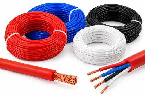
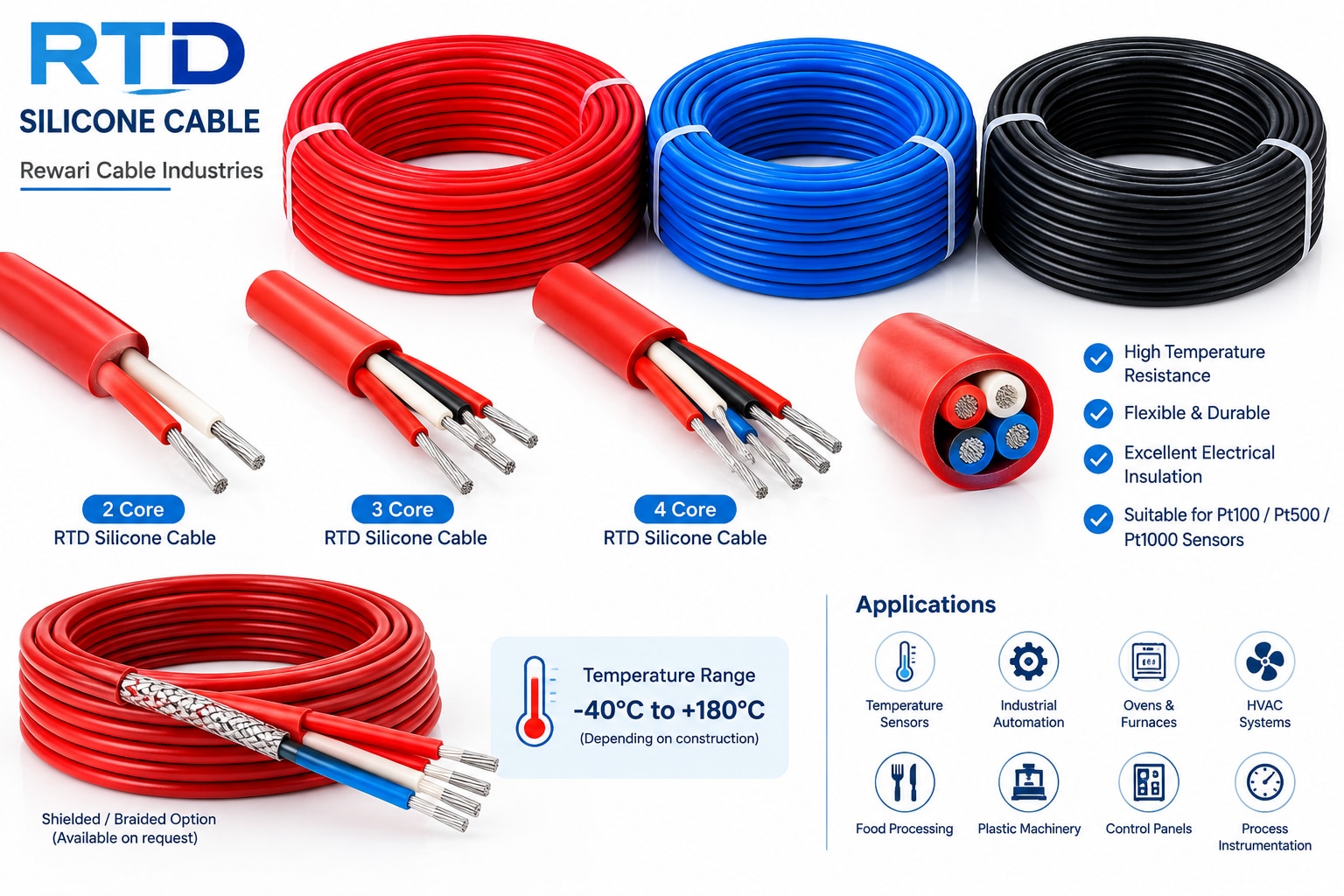 | RTD Silicone Cable Rewari Cable Industries offers RTD Silicone Cables designed for temperature measurement and signal transmission in industrial environments. View product → |
Frequently asked questions
How does lead resistance change a Pt100, Pt500 or Pt1000 reading?
The instrument adds lead resistance to the sensor resistance, creating a temperature error. The same lead resistance causes a larger percentage error in Pt100 than in Pt500 or Pt1000.
When should you use 2-wire, 3-wire or 4-wire RTD connections?
Use 2-wire connections for short runs where lead error is acceptable, 3-wire connections for common industrial compensation, and 4-wire connections when the highest measurement accuracy is required.
How should you specify RTD cable construction?
Specify conductor material and size, insulation temperature rating, shielding, number of cores, overall jacket, flexibility, and resistance limits for the installation environment.
How do you match the complete RTD loop to the instrument?
Confirm the sensor type, IEC 60751 curve, nominal resistance, wiring configuration, input range, excitation method and installation conditions against the instrument datasheet.
What should an RTD wire manufacturer document before supply?
Request the resistance class, conductor details, insulation and jacket materials, temperature ratings, cable resistance, wiring configuration, test results and traceable batch identification.