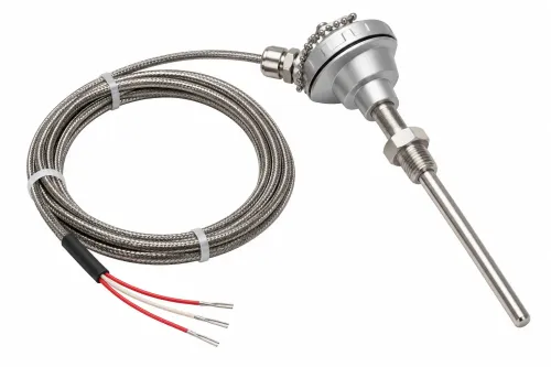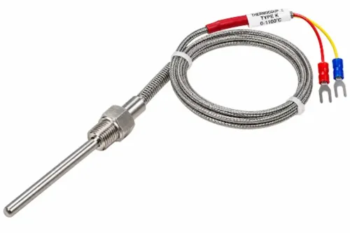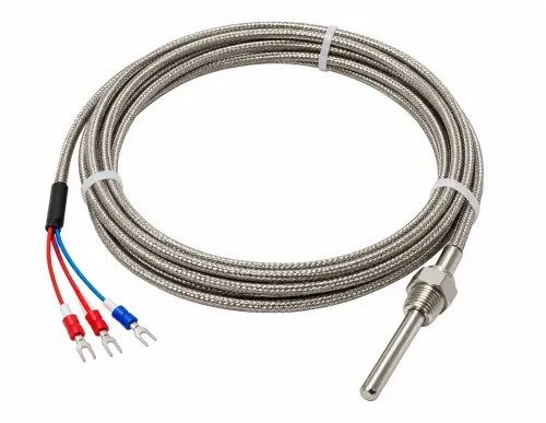
A furnace cable is selected by its actual route, heat exposure, electrical load, atmosphere, movement, and termination—not by a headline temperature rating. By the end, you will be able to separate power, sensor, and extension wiring, compare construction options, specify thermocouple cable correctly, and give a manufacturer a quotation brief that prevents avoidable failures.
Key takeaways
- Map wall penetrations, terminals and radiant heat—not only chamber temperature.
- Use mineral insulation or metal protection when heat, atmosphere or movement demands it.
- Keep thermocouple extension cable separate from furnace power wiring.
- Specify sensor type, polarity, calibration and temperature limits on every cable order.
Map Every Furnace Zone Before Choosing a Cable
Record every furnace location separately; furnace cable selection based on chamber temperature alone fails at the wall penetration or termination. Measure the continuous operating temperature, short-term exposure temperature, ambient temperature and conductor temperature at each point, including radiant heat from doors, elements and refractory surfaces.
| Zone | Thermal reality | Mechanical and electrical check |
|---|---|---|
| Hot chamber | Highest continuous and radiant heat | Check insulation, conductor, sheath, abrasion and atmosphere compatibility; allow for door movement |
| Furnace wall or exit | Rapid temperature gradient and concentrated bending | Specify bend radius, strain relief, gland and transition length; rate the complete termination |
| Control cabinet | Lower ambient temperature but restricted airflow | Recalculate ampacity and voltage drop at conductor temperature; check connector and terminal ratings |
For heater leads, do not copy a room-temperature ampacity table. Bundling, poor airflow and radiant heat raise conductor temperature, resistance, voltage drop and I²R heating. A cable with heat-resistant insulation still fails if its crimp, lug, ceramic terminal, braid or controller connector exceeds its continuous rating.
For thermocouple cables, map static or continuous-flex service, door-cycle movement, contamination and support points. Specify the cable’s minimum bend radius and strain relief, then rate the weakest part: alloy, insulation, seal, sheath or connector. Keep the transition gradual and place the cold junction in a controlled, accurately sensed area.
Choose the Construction for Heat, Atmosphere and Movement
Temperature rating alone can select the wrong cable. Match the construction to the atmosphere, abrasion, moisture and movement at each point: a chamber lead, wall penetration and control-cabinet run rarely need the same insulation.
| Construction | Furnace-service strengths | Limitations and best use |
|---|---|---|
| Fiberglass cable | Handles high heat and oxidation; flexible and easy to terminate. | Braid abrades, absorbs moisture and offers limited chemical protection. Use where movement is modest and the route is protected. |
| Silicone-fiberglass cable | More flexible, with a resilient silicone outer layer over fiberglass. | Silicone can degrade in oils, solvents and direct radiant heat. Use on cooler furnace approaches and moving door sections. |
| PTFE cable | Excellent resistance to oils, acids and many chemicals; smooth and easy to clean. | Its temperature ceiling is far below ceramic, mica or mineral insulation. Use in cooler contaminated zones, not inside the hot chamber. |
| Ceramic insulated wire | Survives extreme heat and oxidation. | Brittle, abrasion-sensitive and difficult to terminate; support it against vibration. |
| Mica cable | Strong short-term heat and flame resistance. | Mica cracks under repeated bending. Use for fixed hot runs and fire-resistant transitions. |
| Mineral-insulated cable | Compact MgO insulation tolerates heat, vibration and pressure. | Stiff, costly and moisture-sensitive at unsealed cut ends; specify bend radius and strain relief. |
| Metal-sheathed cable | Resists abrasion and contains the insulation. | Adds stiffness and requires sheath-compatible glands and grounding. Check corrosion against fluorides, alkalis and reducing gases. |
Route the hot-to-cold transition gradually. Specify static or continuous-flex service, flex cycles, bend radius and connector temperature; a high-temperature insulation cannot rescue a standard terminal.
Separate Thermocouple Signal Cable from Furnace Power Cable
A thermocouple cable carries a millivolt-level signal; a heater power cable carries substantial current. Treating them as interchangeable can produce a false temperature reading, overheated conductors, or both.
| Cable type | Select it for | Check before specifying |
|---|---|---|
| Thermocouple cable | Sensor-to-instrument signal | Matching thermocouple type, polarity, calibration tolerance, insulation and reference-junction treatment |
| Heater power cable | Furnace heaters and resistance-element leads | Voltage, current at actual conductor temperature, voltage drop, flexing, insulation and termination ratings |
| Instrumentation cable | Low-level control, alarm and feedback circuits | Conductor resistance, shielding, pair construction, noise exposure and electrical separation |
Specify thermocouple-grade wire when the conductors operate across the sensor’s measurement range. Extension-grade wire suits the restricted-temperature section between the thermocouple and a controlled reference junction; placing it in a hot zone can create error even with the correct connector and colour code.
- Locate every dissimilar-metal junction, including copper terminals and splices. The instrument must measure or compensate the cold junction at a known temperature.
- Rate heater and resistance-element leads at their real conductor temperature, not a room-temperature ampacity table. Bundling, radiant heat and poor airflow raise resistance, voltage drop and I²R heating.
- Check insulation against the furnace atmosphere. Oxidation, reducing gases, vacuum, fluorides, oils and abrasion can defeat a temperature-rated cable. Then verify the connector, gland and bend limit—the weakest component sets the usable rating.
Match the Thermocouple Cable to the Sensor and Measurement System
A Type K thermocouple requires a Type K thermocouple cable, not a cable chosen by insulation colour. The conductor alloy, polarity and tolerance must match the sensor and input card.
| Type | Conductor pair to verify |
|---|---|
| Type K thermocouple cable | Nickel-chromium / nickel-aluminium |
| Type J thermocouple cable | Iron / constantan |
| Type T thermocouple cable | Copper / constantan |
| Type E thermocouple cable | Nickel-chromium / constantan |
| Type N | Nicrosil / nisil |
| Type R | Platinum-rhodium / platinum |
| Type S | Platinum-rhodium / platinum |
| Type B | Platinum-rhodium / platinum-rhodium |
State thermocouple-grade or extension-grade cable, plus IEC 60584-3 or ASTM E230/E230M and the required tolerance. Extension-grade conductors used in a hot zone can add error even with the correct connector. Reverse the positive and negative leads and the instrument receives the wrong emf, producing an incorrect reading or fault.
Every transition to copper, a terminal, or another alloy creates a reference junction. Keep the cold junction at a known, stable location, or let the instrument measure it with compensation; a convenient splice at the furnace wall is not automatically accurate.
Route the pair away from heaters, motors, SCRs and ignition wiring. Specify shield termination with the control architecture: grounding both ends can create circulating currents, while a grounded junction plus grounded shield can create a ground loop.
Size the Electrical Circuit and Protect the Weakest Point
Size the circuit from heater current and the hottest termination, not from the insulation label alone. Calculate heater current as P ÷ V for a resistive load, then select a conductor cross-section whose allowable ampacity remains above that current at the actual ambient temperature, conductor temperature, bundling and airflow conditions.
Resistance rises as the conductor heats.
Use the voltage drop calculation Vdrop = I × R, with R based on conductor length, resistivity at operating temperature and cross-sectional area. Check the resulting drop against the heater or controller limit; excessive drop reduces heater output and adds I²R heating. Increase conductor cross-section or shorten the run when necessary.
Confirm the complete route and termination against these checks:
- Apply the manufacturer’s ampacity correction for radiant heat, enclosed routes and grouped cables; never copy a room-temperature table.
- Keep the cable within its specified static or continuous-flex minimum bend radius. Repeated door movement needs strain relief and a flex-cycle rating.
- Verify the terminal temperature rating, lug, crimp, gland and connector at the actual ambient; a cooler-rated termination can fail while the cable survives.
- Rate the weakest assembly point, including the seal or transition, for continuous and short-term exposure in the furnace atmosphere.
Turn the Selection into a Supplier Specification and Inspection Plan
Send the manufacturer a zone-by-zone specification, not “high-temperature cable”: route, continuous and short-term temperatures, ambient temperature, furnace atmosphere, flexing, bend radius, length, conductor size, sensor type, shielding, and termination location. State whether IEC 60584-3 or ASTM E230/E230M governs thermocouple colour and tolerance.
- Require a cable datasheet naming conductor alloy, insulation, braid or sheath, temperature ratings, minimum bend radius, moisture limits, and continuous versus intermittent ratings.
- Require a termination schedule covering lugs, glands, connectors, ceramic terminals, seals, and controller-side connections, with each component’s temperature rating and reference-junction arrangement.
- Request a dimensional drawing, part number, batch traceability, certificate of conformity, and routine test report for continuity, polarity, conductor resistance, and insulation resistance.
- Use a cable quotation comparison that separates cable cost from glands, connectors, heat shields, routing supports, and replacement spares.
Before commissioning, inspect labels against the purchase order, check polarity and sensor type, measure resistance, test insulation at the specified voltage, verify bend radius, and confirm shield grounding at the designed point. Reject crushed insulation, loose braids, unsealed transitions, or a connector rated below the termination temperature.
For a Rewari Cable Industries quotation, require these same documents and checks; a fiberglass construction does not prove that its connector, splice, or furnace-wall transition suits your installation.
Related products
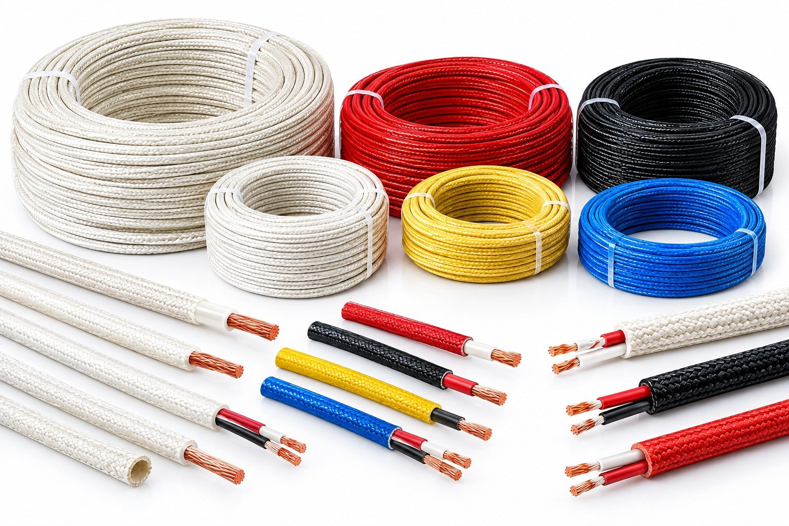 | Fiberglass Cable Rewari Cable Industries Fiberglass Cables and Fiberglass Insulated Wires are designed for electrical and industrial applications requiring... View product → |
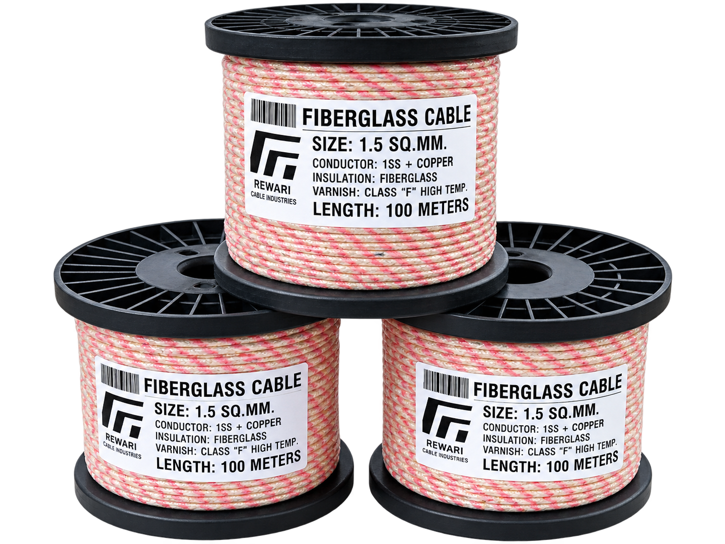 | Fibreglass Cable Rewari Cable Industries manufactures high-quality Fibreglass Cables designed for electrical applications requiring excellent heat resistance,... View product → |
Frequently asked questions
Why must you map every furnace zone before choosing a cable?
Chamber temperature does not describe wall penetrations, terminals or cable routes. Record continuous, short-term, ambient and conductor temperatures at each location, including radiant heat from doors, heating elements and refractory surfaces.
How do you choose cable construction for a furnace application?
Match insulation, shielding, braid, armour and flexibility to heat exposure, furnace atmosphere and cable movement. Select protection for the hottest point and the most demanding mechanical condition.
What is the difference between thermocouple cable and furnace power cable?
Thermocouple cable carries a low-level temperature signal and requires the correct alloy, polarity and insulation. Furnace power cable carries electrical load and requires conductor sizing, insulation ratings and circuit protection.
What information should a supplier specification include?
State each cable route, temperature limits, conductor size, insulation and sheath materials, thermocouple type, polarity, shielding, bend or movement requirements, length, termination details and inspection tests.
Related products
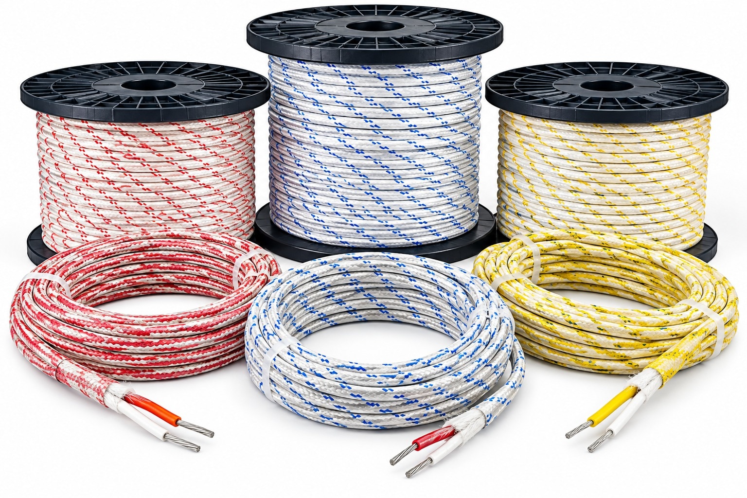 | Thermocouple Fiber Cable Rewari Thermocouple Fiber Cable Rewari Rewari Cable Industries offers high-quality Thermocouple Fiber Cables designed for temperature measurement and signal transmission in demanding... View product → |
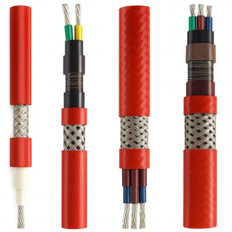 | Heat Trace Cable Rewari Cable Industries offers Heat Trace Cables for controlled electric heating, freeze protection, and process temperature maintenance of pipes,... View product → |
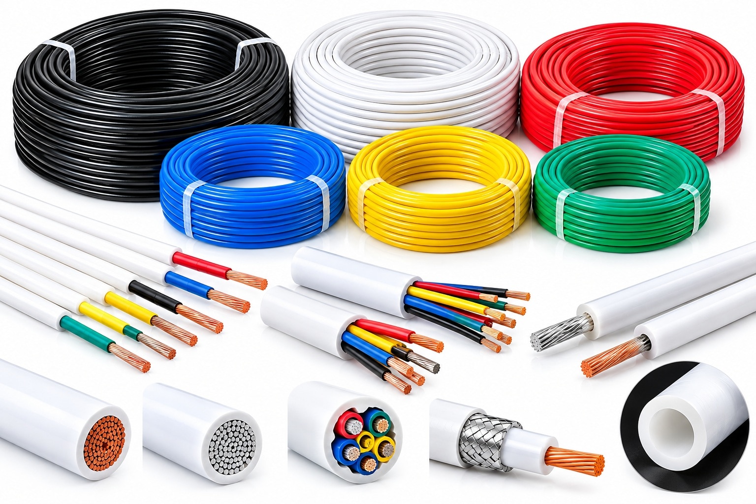 | PTFE Teflon Cable Rewari Cable Industries offers PTFE Teflon Cables designed for electrical wiring and industrial applications where high-temperature performance,... View product → |