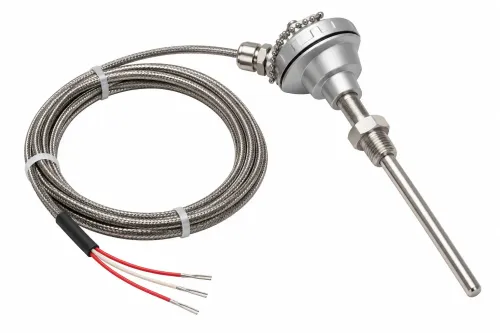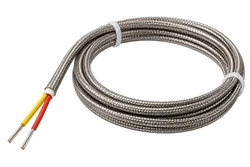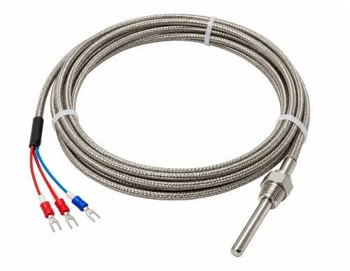
A thermocouple system can show a plausible number while measuring the wrong temperature because of cold-junction error, unsuitable alloys, poor cable selection, electrical noise, or heat conducted away through the probe. By the end, you will be able to select the thermocouple type, junction, cable, sheath, and controller interface as one measurement system and specify the checks needed for credible accuracy.
Key takeaways
- Match the thermocouple type to the process atmosphere and temperature range.
- Keep extension wire, connectors, terminals, and inputs thermocouple-compatible.
- Choose the junction, insulation, sheath, and probe dimensions for the installation.
- Verify polarity, reference-junction compensation, response, and readings before relying on data.
How a thermocouple produces a temperature reading
A thermocouple measures a temperature difference, not absolute temperature. Two dissimilar metal wires joined at the hot junction generate a small voltage through the Seebeck effect. The instrument reads that voltage and uses the known temperature of the reference junction to calculate the hot-junction temperature; it does not measure the hot temperature directly.
The reference junction is where the thermocouple conductors meet the instrument terminals. Its temperature changes with the panel or cabinet, so the instrument needs cold-junction compensation (CJC) to correct the reading continuously. The CJC sensor must sit thermally close to the thermocouple terminal junctions, in a nearly isothermal region.
Without that correction, a stable process can display a changing temperature as the cabinet warms or cools.
- Check that the input is configured for the correct thermocouple type and polarity. A Type K signal is only about 41 µV/°C near room temperature, so small unwanted voltages matter.
- Use matching thermocouple or extension conductors. Copper wire or the wrong alloy creates another thermocouple and adds a temperature-dependent error.
- Keep connectors and terminal junctions clean, correctly matched, and away from heat sources. Electrical noise and unintended dissimilar-metal junctions can exceed the useful signal.
- Calibrate the complete chain when accuracy is critical: sensor junction, cable, connectors, CJC, transmitter or input card, and the installed configuration. Wire tolerance alone cannot reveal installation or instrument error.
Choosing the thermocouple type for the process atmosphere
Temperature alone does not choose the alloy. Match the thermocouple to the process atmosphere, then check whether the supplied wire, insulation, sheath, junction, and exposure time support the stated limit.
| Type | Approximate useful range | Atmosphere and practical choice |
|---|---|---|
| Type K thermocouple | −200 to 1,260 °C | General oxidising or inert service; sulfur, reducing gases, and contamination accelerate drift. |
| Type J thermocouple | −210 to 760 °C | Reducing or inert service; avoid prolonged oxidising exposure because the iron leg oxidises. |
| Type T thermocouple | −200 to 400 °C | Moist, oxidising, reducing, or inert low-temperature work; useful for cryogenic measurement. |
| Type E thermocouple | −200 to 900 °C | Oxidising or inert service; high output helps where electrical noise is a concern. |
| Type N thermocouple | −200 to 1,300 °C | Oxidising or inert high-temperature service; better long-term stability than Type K in many clean furnace applications. |
| Type R or S | 0 to 1,600 °C | Oxidising atmospheres and high-temperature stability; protect against metallic vapours, contamination, and reducing gases. |
| Type B | 600 to 1,700 °C | Very high-temperature oxidising service; its low output makes it unsuitable for low temperatures. |
Treat these ranges as thermocouple-alloy limits, not approval for every construction. Specify IEC 60584-2 class, temperature range, atmosphere, and calibration basis; a thin wire or mineral-insulated probe with moisture ingress can fail well below the nominal limit.
In vacuum, select a sheath and insulation that will not outgas, and verify that furnace contaminants will not attack the chosen alloy.
Keeping the signal chain thermocouple-compatible
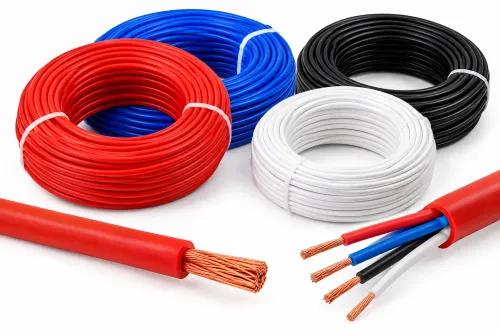
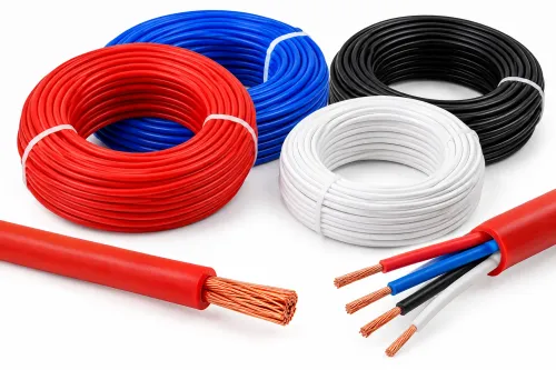
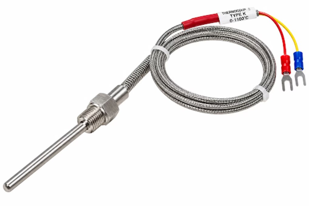
Match every metal and input to the sensor type. A Type K probe needs Type K thermocouple-grade extension wire, Type K connectors, correct polarity, and a controller configured for Type K. Extension-grade wire is not interchangeable with thermocouple-grade wire: it reproduces the thermoelectric response only across its specified temperature range.
A compensating cable uses substitute alloys with the same limitation. Ordinary copper adds dissimilar-metal junctions and creates a temperature-dependent error.
Check the signal chain before installation:
- Read the sensor marking and match the cable, connector, and controller input to that type.
- Confirm positive and negative conductors using the manufacturer’s marking, not insulation colour alone.
- Apply one standard for thermocouple connector colour coding, such as ANSI/ISA MC96.1 or IEC 60584-3; the colours are not identical between standards.
- Keep connector gender and polarity consistent. Reversed leads produce a reading that moves in the wrong direction as temperature changes.
- Confirm that the controller’s cold-junction compensation is enabled at the thermocouple terminals.
Keep the millivolt signal away from variable-frequency drives, contactors, heaters, and power cables. Terminate the cable shield according to the control-system design rather than grounding both ends by default. For traceable accuracy, calibrate the complete installed chain: junction, cable, connectors, cold-junction sensor, input card or transmitter, and mounting arrangement.
A bare-wire calibration cannot reveal errors from thermal gradients, compensation, installation, or electronics.
Selecting the junction, insulation, sheath, and probe dimensions
A grounded junction transfers heat quickly, but it electrically connects the thermocouple circuit to the sheath. Choose it only when the sheath can share the equipment ground without creating a ground loop or common-mode noise.
| Option | Electrical behaviour | Choose when |
|---|---|---|
| Grounded junction | Fast response; sheath-connected circuit | The installation is electrically quiet and rapid response matters |
| Ungrounded junction | Electrical isolation; slower heat transfer | A grounded machine, variable-frequency drive, or noisy input threatens signal stability |
| Exposed junction | Fastest response; least physical protection | Clean, noncorrosive air or liquid permits direct exposure |
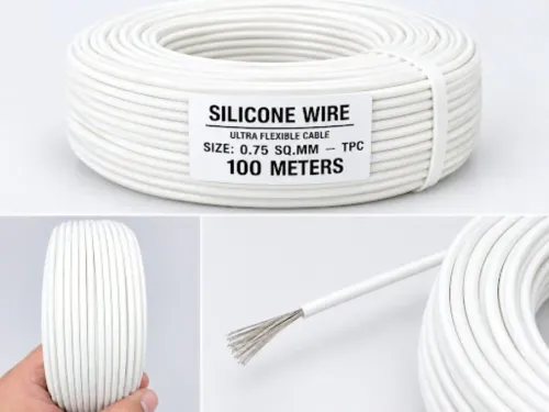
Fiberglass insulation versus silicone insulation versus PTFE insulation versus mineral-insulated cable requires a process-specific choice. Fiberglass suits higher-temperature dry service but absorbs moisture and offers limited abrasion resistance. Silicone handles flexibility and moisture better, yet its temperature limit is lower than many fiberglass constructions.
PTFE resists chemicals and moisture, but confirm its maximum temperature before installation. Mineral-insulated cable provides a compact, rugged metal sheath for high temperature and small diameters; seal its ends, because moisture ingress lowers insulation resistance, and avoid severe bending.
Specify the dimensions with the mounting hardware installed:
- Select the smallest sheath diameter that survives vibration, abrasion, pressure, and corrosion; a heavy sheath slows response.
- Immerse the sensing junction far enough to avoid wall and surface-temperature errors, while keeping the unsupported length short.
- State a response-time target with the sheath diameter, junction construction, flow, and mounting method. A bare exposed junction’s time is not comparable with a sheathed probe’s time.
- Confirm the insulation, weld, sheath, and exposure duration support the actual process temperature; the thermocouple type’s nominal range does not guarantee that wire construction.
Installing and verifying a complete temperature measurement system
A correct sensor can still produce a wrong reading if thermocouple installation puts the junction in a wall boundary layer, outside the process stream, or beside a heat source. Insert enough length to reach the representative temperature zone, support the probe against vibration, and prevent contact with the opposite metal surface.
Check for temperature gradients and thermal shunting through the sheath.
Keep the cold-junction compensation sensor thermally close to the thermocouple terminal junctions in a nearly isothermal area. Use the matching thermocouple-grade or specified extension cable throughout; copper wire or the wrong alloy creates another thermocouple. Route the cable away from variable-frequency drives, contactors, heaters, and power conductors to limit electromagnetic interference.
Apply shield grounding according to the control-system design, not at both ends by default.
Ask the supplier to state:
- Thermocouple type, IEC 60584-2 Class 1, applicable temperature range, and calibration basis
- Tolerance as a temperature-dependent limit: for Type K Class 1, ±1.5 °C or ±0.004|t|, whichever is greater
- Extension or compensating cable type, polarity, insulation, and maximum service temperature
- Junction construction, insulation resistance, response test, and serial or batch identification
- Results for the complete thermocouple calibration chain, including cable, connectors, cold-junction compensation, input card, and installation configuration
Rewari Cable Industries can be asked to document those interface details rather than quoting “Type K” alone. Verify the assembled system at its operating points with a traceable reference, then investigate drift, transmitter error, gradients, and installation error separately; wire tolerance excludes them.
Related products
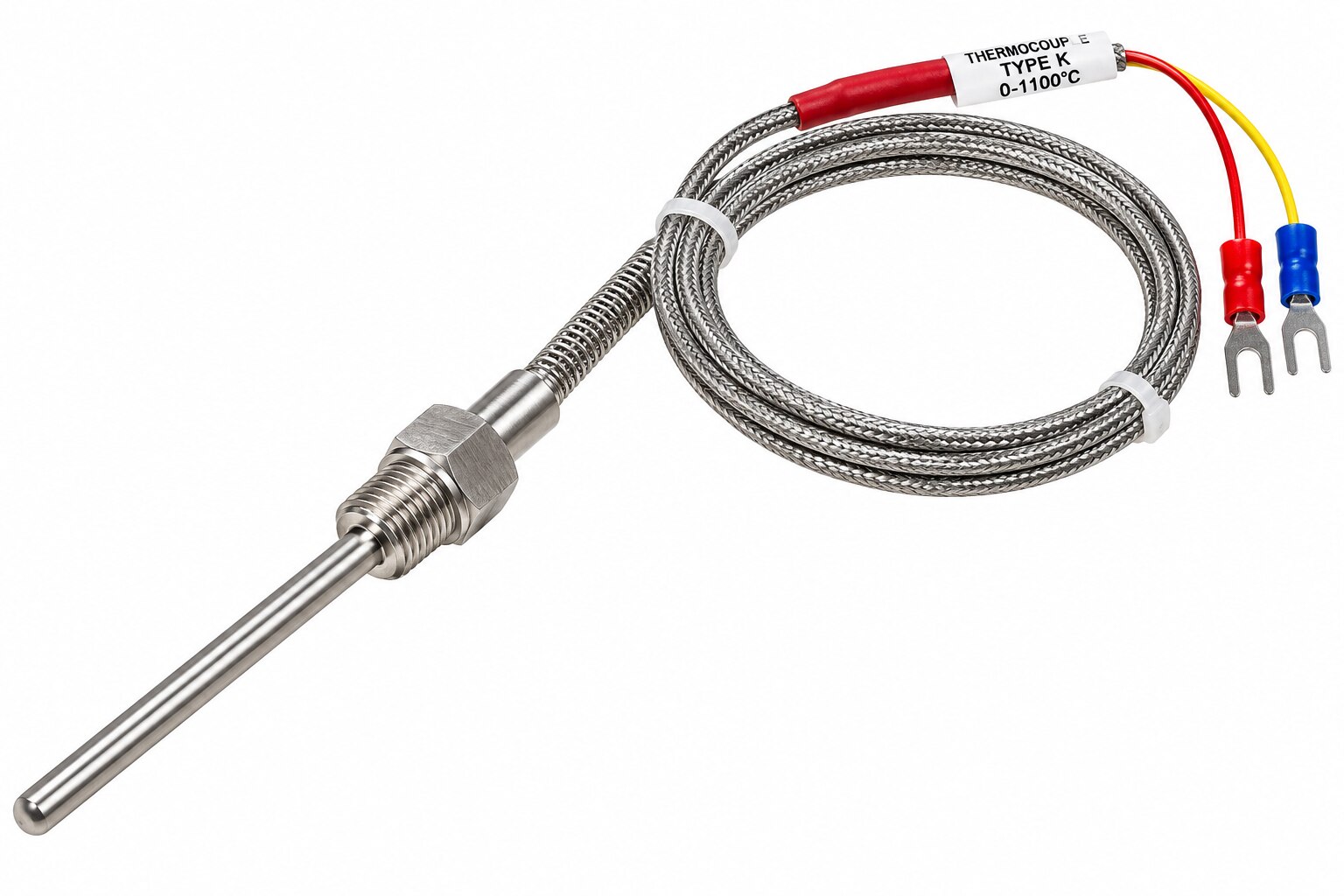 | Thermocouple Sensor Manufacturer & Supplier Rewari Cable Industries offers reliable and high-quality Thermocouple Sensors designed for accurate temperature measurement... View product → |
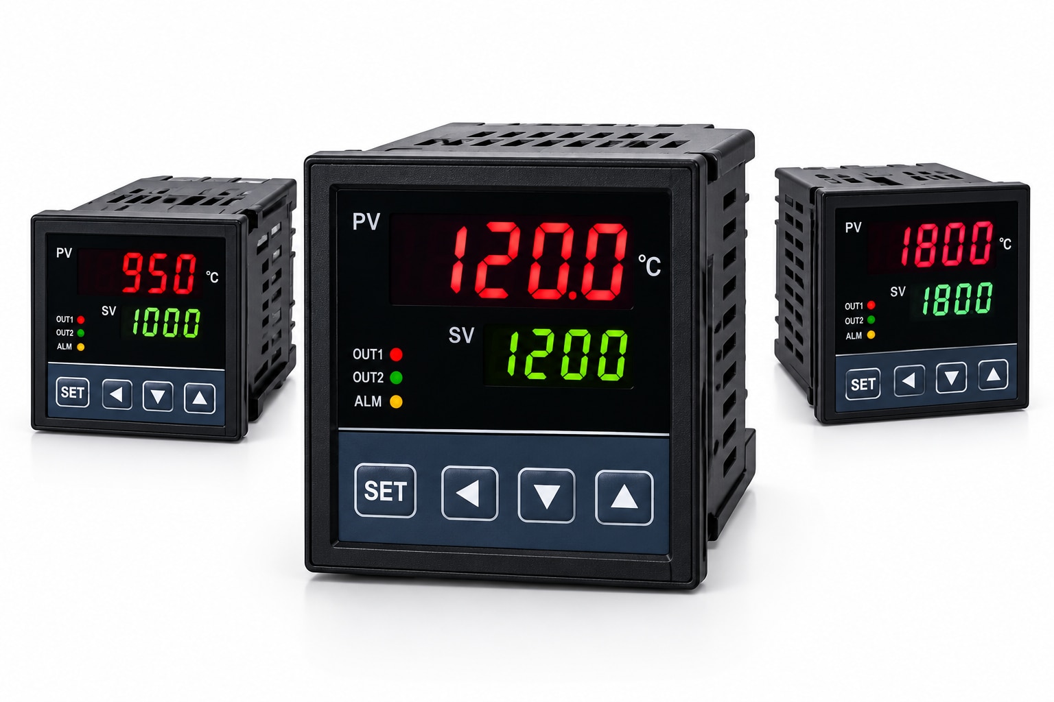 | Digital Temperature Controller Digital Temperature Controller Rewari Cable Industries offers digital temperature controller solutions designed for accurate temperature monitoring and automatic control in... View product → |
Frequently asked questions
How does a thermocouple produce a temperature reading?
Two dissimilar wires joined at a hot junction generate a Seebeck voltage. An instrument combines that voltage with the reference-junction temperature to calculate the hot-junction temperature.
How do you choose a thermocouple type for a process atmosphere?
Compare the thermocouple type with the process temperature range, oxidation or reduction conditions, contamination, and compatibility with the surrounding atmosphere.
Why must the signal chain remain thermocouple-compatible?
Use the correct thermocouple extension wire, polarity, connectors, terminals, and input configuration. Ordinary copper wire or mismatched connectors introduce additional junctions and measurement errors.
What should you consider when selecting a thermocouple probe?
Select the junction style, insulation, sheath material, diameter, and insertion length based on response time, electrical isolation, mechanical protection, and process compatibility.
How do you verify an installed thermocouple measurement system?
Check polarity and wiring, confirm reference-junction compensation, inspect the installation, compare the reading with a suitable reference, and document the test conditions.
Related product
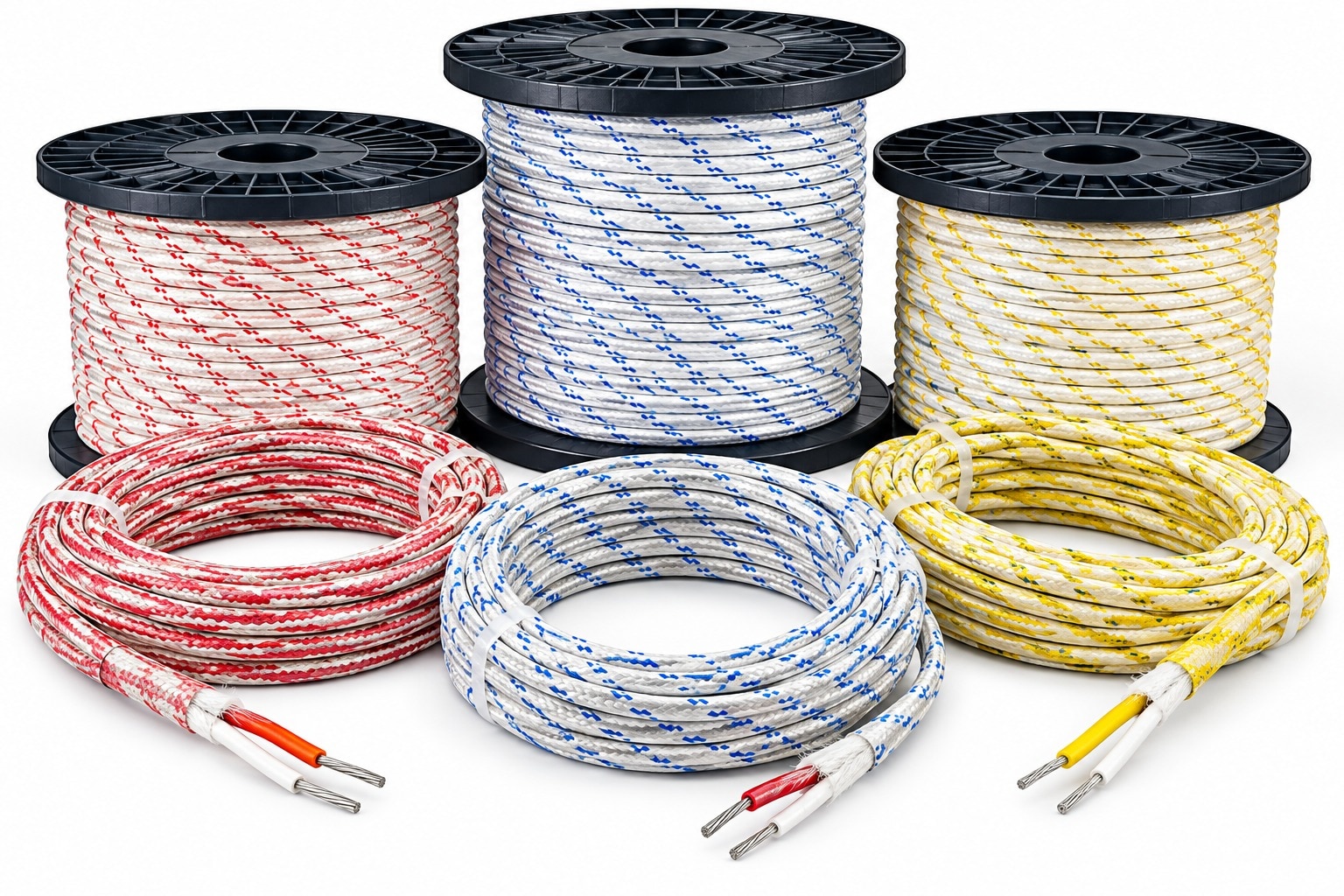 | Thermocouple Fiber Cable Rewari Thermocouple Fiber Cable Rewari Rewari Cable Industries offers high-quality Thermocouple Fiber Cables designed for temperature measurement and signal transmission in demanding... View product → |