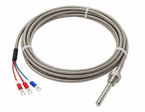
Choosing a head-mounted RTD manufacturer requires more than comparing Pt100 prices or headline temperature ranges. You need to match the sensing element, connection head, thermowell, transmitter, materials, approvals, and calibration evidence to the process so the complete installed assembly delivers a dependable measurement.
Key takeaways
- Specify a Pt100 RTD meeting IEC 60751 accuracy requirements.
- Match probe length, sheath material, and thermowell to process conditions.
- Choose lead configuration and transmitter output for your control system.
- Request calibration records, test data, and documented supplier capabilities.
Define the Head-Mounted RTD Assembly and Its Role in the Process
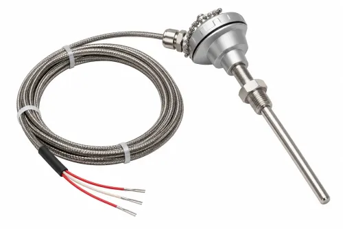
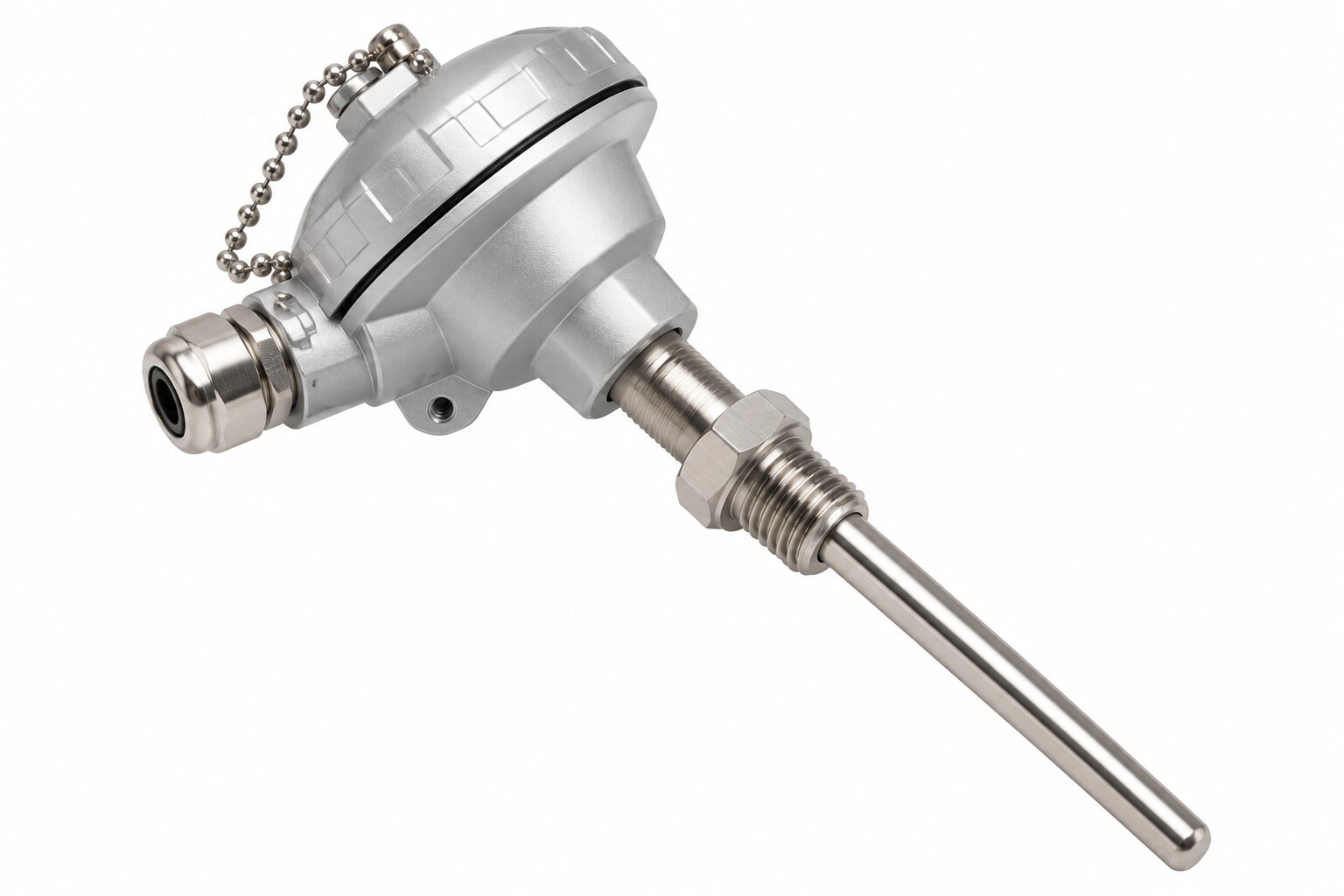
A head-mounted RTD sensor is a resistance temperature detector whose probe terminates in an RTD sensor head fixed directly above a thermowell, process vessel, pipe, furnace, heater, exhaust line, or machine measurement point.
The head contains terminals or a head-mounted transmitter, so the assembly connects locally rather than sending the probe leads to a distant terminal box.
Use this decision sequence for process temperature measurement:
- Choose a head-mounted RTD when you need IEC 60751 resistance accuracy, stable readings, and a compact service point beside the thermowell. Verify the complete assembly’s temperature limit; the head, gasket, cable gland, terminal block, and transmitter can fail before the element reaches its advertised rating.
- Choose a thermocouple when you need a wider temperature range, faster response, or operation where RTD wiring and self-heating are unacceptable. In a thermocouple comparison, account for reference-junction compensation and lower signal levels.
- Choose a remote-terminal RTD when heat, vibration, access restrictions, or hazardous-area separation would damage electronics at the process connection.
- Choose a transmitter when long 4–20 mA runs and noise immunity outweigh added electronics, configuration, ambient-temperature error, and another failure mode.
- Choose a fixed industrial thermometer for local indication only, where control-system input, calibration records, and remote alarming are unnecessary.
Ask for self-heating data at the actual excitation current; I²R power can create a measurement error inside the finished assembly.
Check the RTD Element, IEC 60751 Accuracy, and Lead Configuration
At 600 °C, IEC 60751 Class A allows ±1.35 °C element tolerance, while Class B allows ±3.30 °C. These limits apply only to the RTD element, not the transmitter, lead wires, input card, installation, drift, or calibration uncertainty.
| Element | Resistance at 0 °C | Practical selection |
|---|---|---|
| Pt100 | 100 Ω | Standard industrial choice; verify lead resistance and input compatibility |
| Pt500 | 500 Ω | Middle option when you want more signal than Pt100 without Pt1000’s greater excitation sensitivity |
| Pt1000 | 1,000 Ω | Useful with long wiring or low-current inputs; check self-heating and input-card limits |
Select the element that matches the control system, measuring current, cable length, and required error budget. Ask the manufacturer to state IEC 60751 compliance, the reference coefficient of 0.00385 Ω/Ω/°C, and whether the quoted Class A or Class B RTD accuracy applies to the element, complete assembly, or sensor-plus-transmitter loop.
A nominal “Pt1000” label alone proves none of those points.
Confirm self-heating at the actual excitation current because power is approximately I²R. Then specify the wiring arrangement:
- Two-wire circuits add both lead resistances to the reading.
- Three-wire circuits cancel lead resistance only when the relevant leads closely match.
- Four-wire circuits provide the strongest lead-resistance rejection.
Require cable resistance and temperature limits, transmitter accuracy, ambient effect, linearization, damping, burnout response, and loop-power requirements in writing. A Class A element does not make the finished installation Class A.
Match the Probe, Thermowell, and Mounting Hardware to the Process
Approve the assembly only after the manufacturer matches the probe, thermowell, and mounting hardware to the process’s temperature, pressure, chemistry, dimensions, and vibration. A high element-temperature rating does not qualify a complete installation: the sheath, mineral insulation, transition, head, gasket, cable gland, and transmitter each impose a limit.
| Application | Evidence to approve | Failure if ignored |
|---|---|---|
| Vessel or pipe | Pressure-boundary design, corrosion allowance, flow velocity, insertion length, probe diameter and mounting thread; thermowell calculations to ASME PTC 19.3 TW | Leakage, deformation, or wake-frequency fatigue |
| Furnace, heater, or exhaust | Sheath compatibility with oxidation, carburization, sulfur, halides, erosion, and thermal shock; drift and insulation-resistance results after thermal cycling | Early drift, insulation breakdown, or sheath failure |
| Machine or vibrating line | Vibration qualification for the assembled probe, thermowell, head, cable entry, and support; confirm wake-frequency margin | Cracked sheath, loosened terminals, or intermittent readings |
Ask for a drawing showing immersion depth, clearances, thread, flange, weld pad, and head position. Do not accept a response-time number without test conditions: exposed tips respond faster than mineral-insulated probes in a thermowell, while flow velocity, sheath diameter, immersion depth, and the response criterion change the result.
For hazardous service, demand approval for the complete intended configuration, including the sensor, head, transmitter, cable entry, terminals, grounding, separation distances, and protection concept under the applicable IEC 60079 or ATEX route. An approval covering only the transmitter does not approve the assembled sensor.
Evaluate the Connection Head, Transmitter, and Industrial Environment
A high-temperature RTD element does not make the complete assembly suitable for a hot or hazardous plant. Compare the aluminium and stainless-steel connection head against corrosion, mechanical impact, ambient temperature, and mounting location.
Verify the IEC 60529 IP rating on the assembled sensor, including the cover seal, cable glands, unused entries, drain or breather, and mounting orientation. An IP rating for an empty enclosure proves little.
Signal arrangement changes both installation effort and fault behaviour.
| Option | Strength | Check before approval |
|---|---|---|
| Direct 3-wire or 4-wire RTD | Preserves element measurement accuracy | Confirm cable length, shield termination, terminal layout, and resistance from lead wires |
| 4–20 mA transmitter | Handles long runs and improves noise tolerance | Check accuracy, ambient drift, linearization, damping, burnout, supply voltage, and the transmitter’s temperature limit |
| 4–20 mA with HART communication | Adds configuration and diagnostic access | Confirm HART compatibility, loop resistance, wiring, and configuration control |
Require EMC evidence for the actual site under IEC 61326-1. Ask where the shield terminates, how RTD cables stay segregated from variable-frequency drives, contactors, and heater wiring, and what surge and supply conditions the transmitter tolerates. Shielded cable alone does not guarantee immunity.
Rate the complete assembly by its lowest limit: element, sheath, transition, terminals, gasket, gland, head, and electronics. For hazardous areas, demand approval for the exact configuration and installation method under IEC 60079 or ATEX, covering cable entry, terminals, spacing, grounding, and protection concept. An approval for one transmitter does not approve the assembled sensor.
Demand Evidence for Accuracy, Calibration, Reliability, and Supplier Capability
A Class A element certificate does not prove a Class A installed measurement. At 600 °C, IEC 60751 Class A permits ±1.35 °C and Class B permits ±3.30 °C; neither figure includes the transmitter, lead resistance, installation, drift, or calibration uncertainty.
Ask for evidence covering the assembled head-mounted RTD, not merely an interchangeable sensing element:
- An ISO/IEC 17025 calibration report naming the actual sensor, or a justified representative, with calibration points, test method, as-found and as-left results, and measurement uncertainty. A certificate marked only “calibrated” proves little.
- A stated accuracy budget that combines element tolerance, transmitter accuracy, cable resistance, input-card or display error, and calibration uncertainty. Require the supplier to identify whether its figure applies to the element, assembly, or complete loop.
- Self-heating data at your actual measuring current. Heating is approximately I²R, but the resulting error depends on element resistance, assembly heat dissipation, and process conditions.
- Thermal cycling and drift results for the intended temperature range, including post-test insulation resistance. Repeated shock, moisture ingress, sheath contamination, vibration, and platinum drift can overwhelm the initial calibration.
- A wiring and cable schedule stating conductor resistance and temperature limits. Two-wire leads add both resistances; three-wire circuits depend on matched leads; four-wire circuits reject lead resistance more effectively.
Rewari Cable Industries should be asked to document the selected cable’s resistance and temperature limits alongside the RTD assembly, rather than treating cable choice as a separate purchase.
Frequently asked questions
What should you check in a head-mounted RTD assembly?
Check the RTD element, IEC 60751 accuracy class, lead configuration, probe, thermowell, connection head, transmitter, and mounting hardware.
How do you match an RTD probe and thermowell to a process?
Compare the required temperature range, pressure, chemical exposure, flow, insertion length, sheath material, and thermowell construction with process conditions.
What evidence should an RTD manufacturer provide?
Request calibration records, accuracy test results, material details, dimensional drawings, reliability information, and clear documentation of manufacturing capability.
When should you specify a head-mounted transmitter?
Specify one when the installation needs a standardised signal such as 4–20 mA or digital communication near the sensor, provided it suits the environment and control system.